High-speed imaging chart
Courtesy of Dr Phillip Reu from Sandia National Laboratories.
 This chart reports most of the high speed cameras available on the market. Each rectangle is proportional to the image size and the coloured circular sectors represent shutter times as a fraction of interframe time (corresponding to the whole greyed circle).
High speed cameras occupy the top left of the chart, providing long record times but limited frame rates. Rectangles get smaller as the frame rate goes up, reflecting the fact that spatial resolution needs to be compromise to increase temporal resolution, as the limiting factor for the frame rate is the memory transfer time. On the other hand, ultra-high speed cameras (bottom of the chart) use different strategies to adoid this limitation:
- Gated intensified cameras: technology based on beam-splitting with multiple CCD sensors which only capture one image. This leads to very high frame rates but very small record lengths (camera to the far right).
Vendors: Specialized Imaging Ltd (SIM cameras), Cordin.
The main issue with this technology lies in the image intensifiers which create significant blurring of the images, compromising the quality of deformation measurements through DIC or the grid method. Another difficulty is that each sensor sees a slightly different field of view as the optical paths are different. Also, the brightness and contrast from each sensor will be slightly different. Therefore, images can only be correlated from a same sensor. This requires to capture a stationary film first and to use a reference image per sensor.
Examples of the use of such a camera to perform DIC can be found here:- Pierron F., Sutton M.A., Tiwari V., Ultra high speed DIC and Virtual Fields Method analysis of a three point bending impact test on an aluminium bar, Experimental Mechanics, vol. 51, n° 4, 537-563, 2011. http://dx.doi.org/10.1007/s11340-010-9402-y
- Le Louëdec G. Pierron F., Sutton M.A., Siviour C., Reynolds A.P., Identification of the dynamic properties of Al 5456 FSW welds using the Virtual Fields Method, Journal of the Dynamic Behaviour of Materials, vol. 1, n° 2, 176-190, 2015. http://dx.doi.org/10.1007/s40870-015-0014-6
- Rotating mirror cameras: the idea is similar to the above except that to avoid the issue of the light intensity being split in as many channels as there are CCD sensors, a rotating mirror is used to spread the light to a series of sensors mounted onto a drum. This avoids the need for image intensifiers. However, the rotation of the mirror limits the frame rate to a few Mfps, and also tends to create vibrations in the drum which can affect the deformation measurements.
Vendor: Cordin.
The same limitation as for the Gated Intensified cameras applies as per the fact that each sensors has different characteristics and sees a slightly different scene, hence the same requirement for the reference images. On the chart, these cameras are the ones with the larger spatial resolution.
An example of the use of such a camera to perform DIC can be found here:
Moulart R., Pierron F., Hallett S.R., Wisnom M.R., Full-field strain measurement and identification of mechanical properties at high strain rate, Experimental Mechanics, vol. 51, n° 4, pp. 509-536, 2011. http://dx.doi.org/10.1007/s11340-010-9433-4
- In-situ image storage cameras: the idea here is store the data on the chip through solid state technology (channelling electrons to different wells attached to a single photogate) to work around the pixel readout time barrier. The downside of this technology however is that a lot of space on the chip has to be dedicated to storing the data and hence, the spatial resolution of these cameras is generally lower than that of the above. On the chart, they correspond to the two small red dots and the larger light blue rectangle.
Vendors: Specialized Imaging Ltd (Kirana camera), Shimadzu (HPV-X2 and HPV-2 cameras).
The HPV-2 camera, which is based on a dedicated IS-CCD sensor which had some imaging issues detailed in Rossi M., Pierron F., Forquin P., Assessment of the metrological performances of an ISIS ultra-high speed camera for full-field deformation measurements, Measurement Science and Technology, vol. 25, n°2, pp. 025401, 2014. http://dx.doi.org/10.1088/0957-0233/25/2/025401.
However, these cameras represent a significant breakthrough with their ease of operation, single sensor technology (fit for stereo-DIC), ease to trigger (post-triggering is possible) and performances ideal for material testing (5 Mfps).
Examples of the use of such cameras to measure deformation in materials:- Pierron F., Forquin P., Ultra high speed full-field deformation measurements on concrete spalling specimens and stiffness identification with the Virtual Fields Method, Strain, vol. 28, n° 5, pp. 388-405, 2012. http://dx.doi.org/10.1111/j.1475-1305.2012.00835.x
- Pierron F., Zhu H., Siviour C., Beyond Hopkinson’s bar, Philosophical Transactions of the Royal Society A, vol. 372, n° 2023, pp. 20130195, 2014.
http://dx.doi.org/10.1098/rsta.2013.0195 - Zhu H., Pierron F., Exploration of Saint-Venant’s principle in inertial high strain rate testing of materials, Experimental Mechanics, vol. 56, n° 1, pp. 3-23, 2016.
http://dx.doi.org/10.1007/s11340-015-0078-1 - Pierron F., Addendum to “Characterising the strain and temperature fields in a surrogate bone material subject to power ultrasonic excitation”, Strain, in press, 2016.
As part of this project, we are using a Shimadzu HPV-X camera capable of recording 128 images at 5 Mfps. It should be noted that the HPV-X2 camera is about 8 times more sensitive that the HPV-X, but at the cost of increased grey level noise. This is illustrated in the figure below where the temporal evolution of three pixels (from dark to light grey level values) as a function of time, from a stationary scene, has been plotted. The higher noise from the HPV-X2 sensor (in red) is clear compared to the HPV-X (between two and three times more noise). The standard deviation in time normalized by the total number of grey levels is about 0.5% for the HPV-X, and about 1.2% for the HPV-X2 (compared to typically 0.7% for a standard CCD camera). As this project aims at measuring strain and acceleration as accurately as possible for quantitative exploitation, the HPV-X camera provides a significant advantage over the HPV-X2, though it is not available anymore on the market.
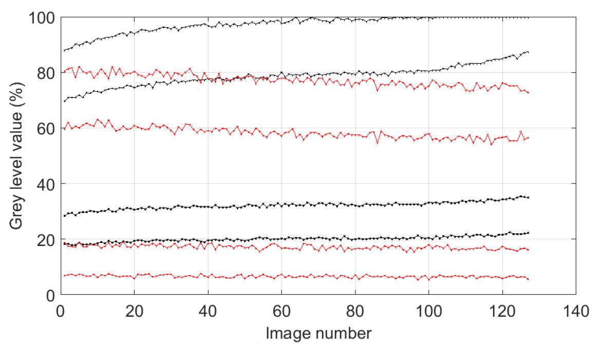
Grey level noise comparison between Shimadzu HPV-X and HPV-X2.
Benchmark of HPV-X vs Kirana cameras
Press the ‘menu’ button on the player to view slide notes